agile-requirements-framework
An Agile Way of Writing Use Cases
This article provides guidance on writing use cases in general and more specifically so they work as the framework to support the way-of-working in the main article about my proposed requirements framework.
Use Case Organization and Format
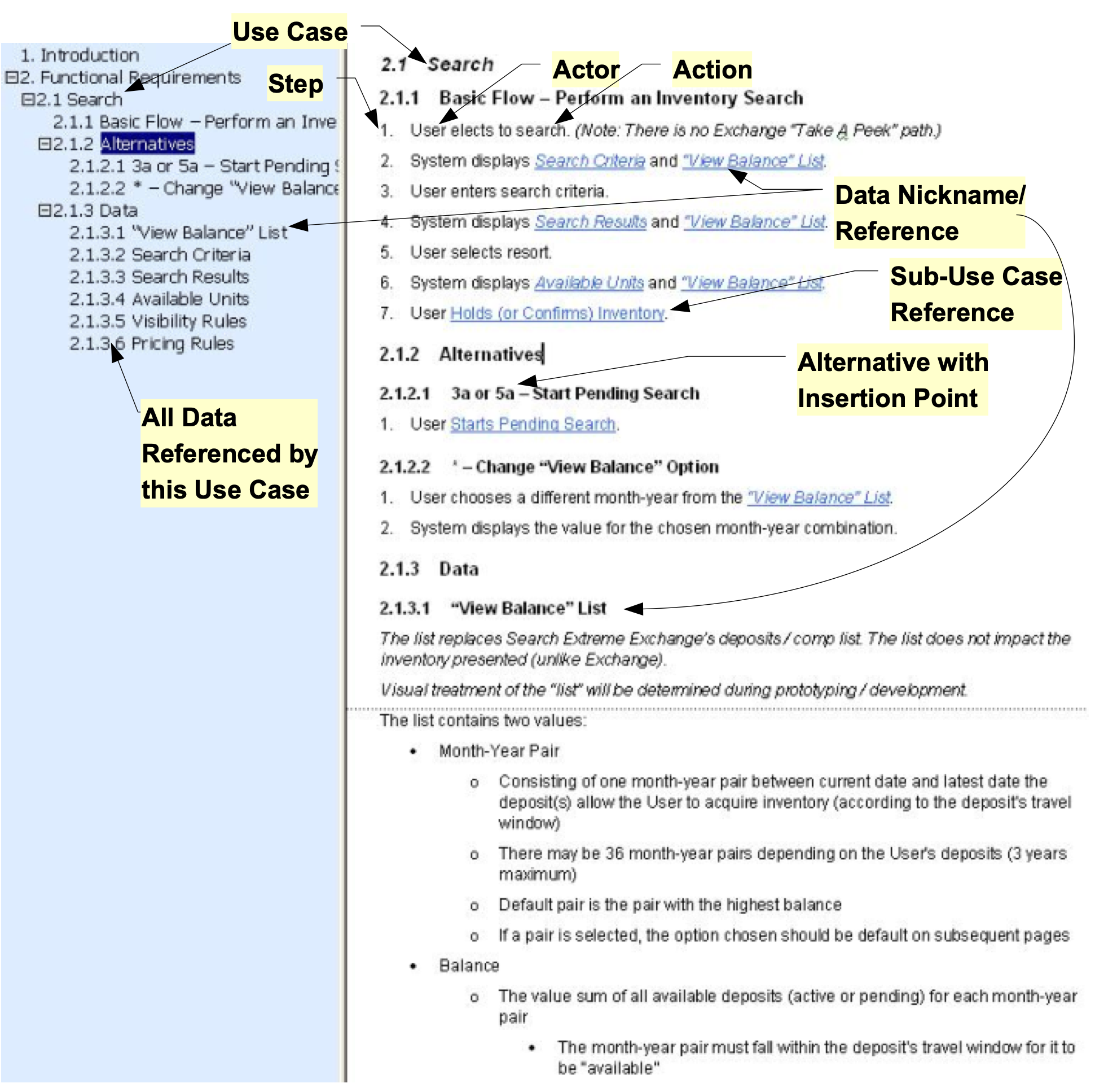
- Each use case has a unique name. It should be the name of a user goal. It should describe the action the user takes to accomplish their goal. It should be a phrase that will fit well if it is included in another use case that refers to it. be an active phrase.
- A use case is a sequence of steps that define the flow done to accomplish the goal. Steps are written in the form: Actor does Action, e.g., “User selects accesses Configuration Designer”.
- The actor can be the user or the system. It’s not worth forcing alternation between user and system steps. Instead focus on the minimum set of steps that tell the story, e.g., lots of times I blend what the system does into the step done by the actor.
- Each step in a use case is assigned a number. This serves to both identify and sequence the steps. In markdown you can use any number and when the document is rendered a correct sequential number will be displayed. Make the effort to keep the numbers sequential so they can be referred to in the definition of an alternative.
- Each use case starts with a Basic Flow that is the most common or simplest sequence of steps, e.g., the case where nothing goes wrong.
- A use case does not include decisions or branches. Instead at any point where there is an alternative, an Alternative Flow is defined. The alternative is assigned an identifier that indicates where it can optionally be inserted into the Base Flow. For example, if the Base Flow had steps 1-3, then an alternative that can be done at step 2 would be assigned the id of “2a – Name of Alternative”. Subsequent alternatives that can be done at the same place would be assigned ids like 2b, 2c, etc. If an alternative can occur in multiple places it is assigned the id of “*” (using the asterisk as a wildcard). If an alternative is a complete replacement for the basic flow it is assigned an id like 1a and 1b to indicate that the alternative replaces step 1 of the basic flow.
- One use case can refer to another (a sub-use case). Such references are formatted with the name of the referenced use as a hyper-link, e.g., Access Designer. The name of the use case is changed slightly to make the step more readable. For example, a step that referenced the Configure Contract Load use case would be written: ‘User Accesses Designer’.
- If a step in a use case accesses complex data or rule, rather than putting the details of it into the step, the data is given a nickname. The nickname is formatted as a hyperlink, e.g., Configuration Tree. The definition of the data or rule is placed in a separate ‘Data’ section below the use case.
- Data that is shared across multiple use cases can be defined in one place, e.g., a ‘Common Data’ section. When an item of data is referenced by a use case the definition of the data in the ‘Data’ section can say ‘Defined in Common Data section’. The data can be found in the ‘Common Data’ section at the beginning of the current document. This is done for data that is used by multiple use cases in the current document.
- Keep the steps short and as simple as possible. They are intended for easy understanding with the details in either the ‘Data Section’ or the ‘Detailed Requirements’ defined by the BDD Scenarios.
- Some use case steps that are external to the application (manual steps) may be included because they are an integral part of the sequence. These steps are tagged with [MS] to indicate they are Manual Steps, Not Tested during Technical Testing. These steps will be tested in User Acceptance Testing where the emphasis is on business processes but not in Unit and System Testing where the emphasis is on technical system testing.
The following figure shows an annotated example of a use case formatted as described above.
Example Use Case
The following is a larger but still simplified example of some use cases for a product to design configuration files. The idea is that a configuration is made up of many parts, each with a unique structure that the user needs to populate.
Access Configuration Designer
Base Flow - Access Designer
- User accesses Configuration Designer by browsing to [designer.com]>(http://designer.com) and enters valid credentials.
- User Opens or Creates a Configuration.
- User Views or Edits Configuration.
- User closes the Configuration.
- User logs-out of the Designer
Alternatives
1a - Setup Credentials
- User starts the Designer for the first time and is prompted to setup >their credentials.
- Continue at step 2
1b - Invalid Credentials
- User enters invalid credentials
- System notifies them of the error and re-prompts up to the allowed >number of times before lock-out.
- Continue at step 1
Detailed Requirement Statements
This section lists the requirements statement / rule for each BDD scenario associated with the use case….
View and Edit Configuration
Base Flow - View and Edit Configuration
- User does any of the following by navigating to the appropriate part of >the configuration.
Data
Configuration Tree
The Tree provides a view of the parts of the Configuration, navigation to >those parts, and operations to create or delete parts where appropriate. >The following is the structure of and the operations available on the >items in the Protocol Tree:
- Config ‘Name’ - with sub-folder for each of the following that when >clicked navigate to and expand to show details of that part of the Config:
- Part-A
- Subparts would be listed here but are omitted to keep the example >simple…
- Part-B
- Subparts…
- Part-C
- Subparts…
Audit Trail
- Operations:
- Part-A
- List the operations available on this tree node and its subparts. >Details omitted to keep the example simple…
- Part-B
- …
Detailed Requirement Statements
BDD scenario associated with the use case….
For details on how the detailed requirements are presented, see Organizing and Managing BDD Scenarios As Your Detailed Requirements
View and Edit Part-A
Base Flow - View and Edit Part-A
- User views or edits the Part-A fields
Detailed Requirement Statements
BDD scenario associated with the use case…